
4K60Hz 4×16 4×12 4×9 Enjoy large screen Seamless Matrix with Video Processor, with 4 free windows


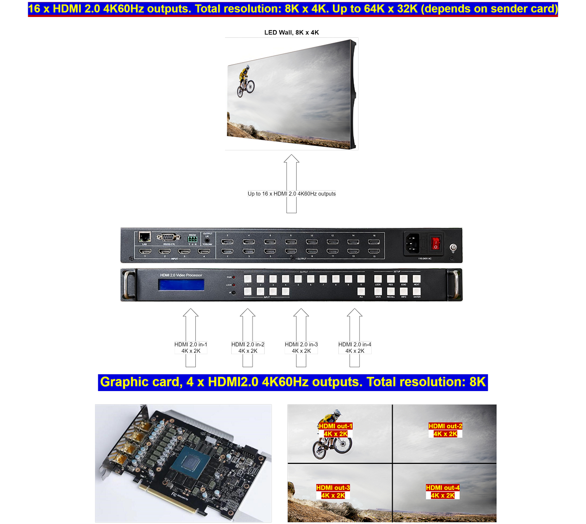
4K 4X16 4×12 4×9 Seamless HDMI Matrix with video Processor,8Kx4K LED Wall
4 Window Multiviewer ,LCD and LED Video Wall Controller
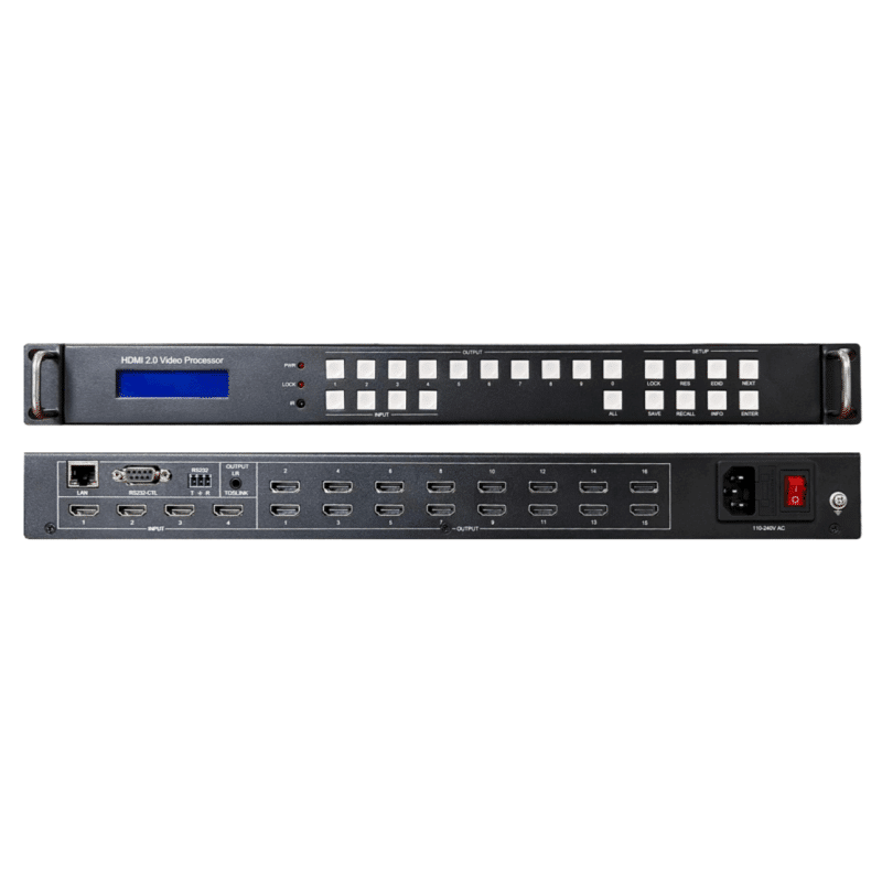
The Video Processor is a high-performance HDMI 2.0 video signal processor.
It can be used as a video wall splicing processor or as a seamless switching matrix switcher with4 inputs and 16 outputs.
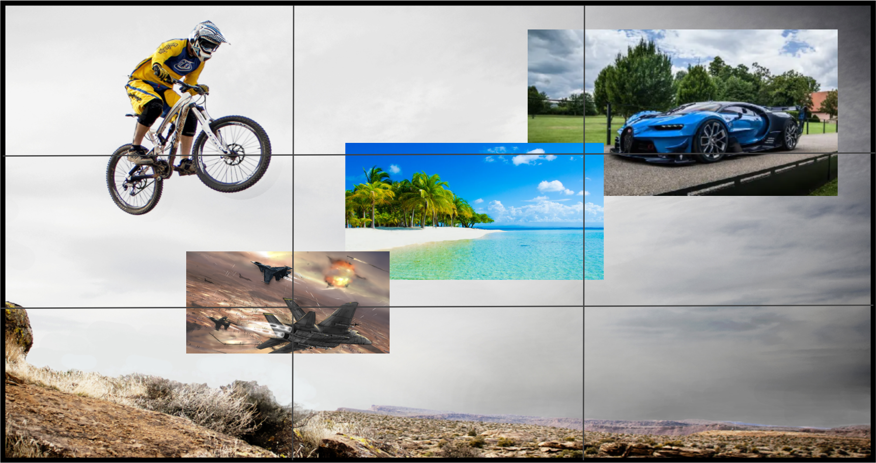
All standalone output display or video wall display can work in multiview mode with a maximum of 4 windows.

Features
- Support seamless switching between different input source
- Comprehensive splicing display function, free multiview up to 4 window
- Support two synchronization mode for all output ports: General synchronization mode and Sync delay mode
- Supports 180° rotation function
- 4 Inputs and 16 Outputs:HDMI 2.0, up to 3840×2160/4096×2160@60Hz resolution
- Support Auto and User Define output resolution, can be flexibly applied to the display of LED wall
- Support one break away audio extractor and switcher
- Provide multiple control ports: front panel buttons, remote control, RS232, network and WebGui control
Interface

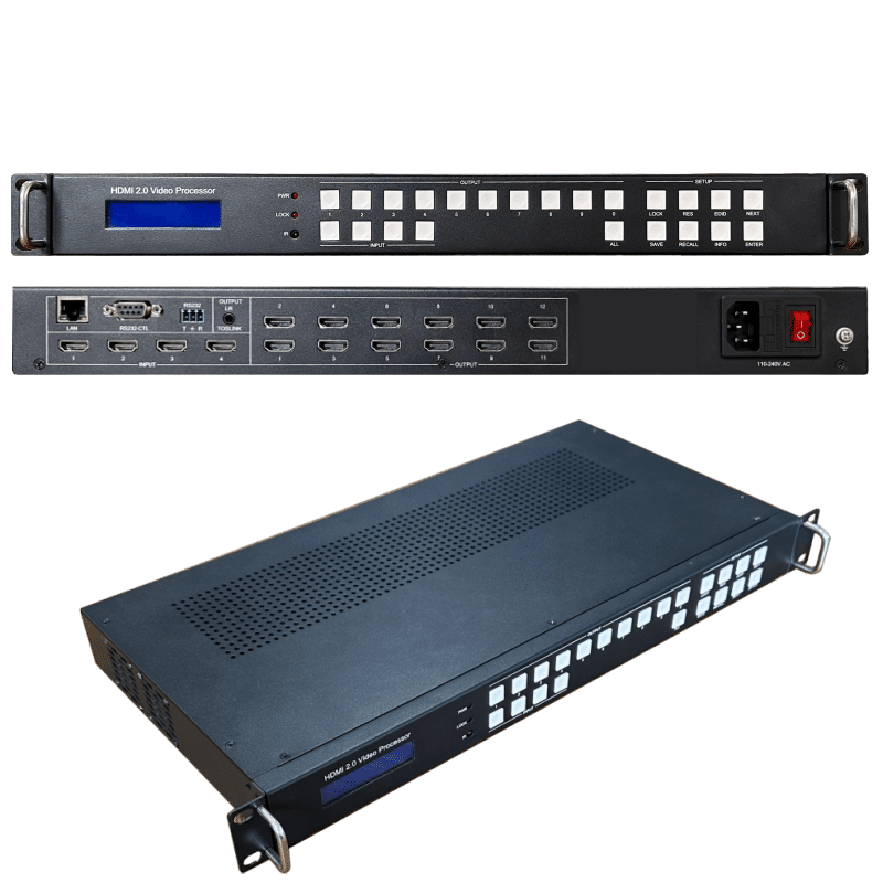
- LCM display screen: displays the routingstatus of each channel in the matrix. Used together with front buttons, it can set and view some parameters
- OUT SELECT:1, ..9, 0, ALL
- IN SELECT:1, 2, 3, 4
Press OUTPUT m +INPUT n +ENTER, switch input n to output m
- ALLbutton: Press ALL + INPUT n +ENTER, switch input n to all output ports
- Lock button : Hold this button more than 3 seconds, all the fronts buttons will be locked and will not work. Holdit more than 3 seconds again, unlock
- Press buttonsRES + OUTPUT m + NEXT + ENTER with guide of front LCM screen display, to change output resolution of OUTPUT m
- Press buttons EDID + INPUT n+ NEXT + ENTER with guide of front LCM screen display, to change the EDID mode of INPUT n
- SAVEbutton : Press SAVE+ OUTPUT m +ENTER, save current routing and screen layout to scene m
- RECALLbutton: Press RECALL+ OUTPUT m +ENTER, load scene m for current displaying
- INFO button: Continuously press INFO button, front LCD panel will loop display IR ON/OFF,RS232 Baud Rate and IP parameters etc,.
- IR: IR receiver, can be disabled by RS232 command

- LAN control(TCP/IP or Web Control)
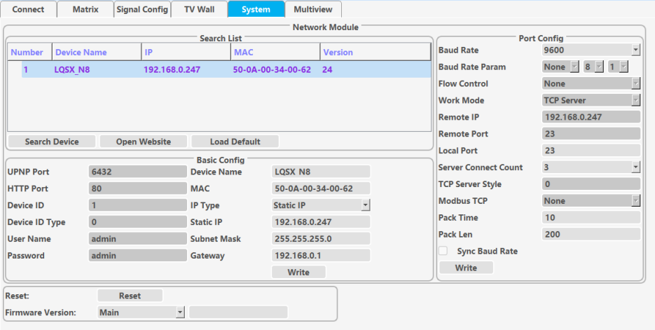
IP address: 192.168.0.247, Submask: 255.255.255.0, Gateway: 192.168.0.1, Baud Rate: 9600, NetPort: 23, Web login account : admin,password : admin
- RS232-CTL Baud Rate: 9600
- RS232-Phoenix: Baud Rate: 9600
T: Main Unit -> PC, G: Ground, R: Main Unit <- PC
- Inputs and outputs
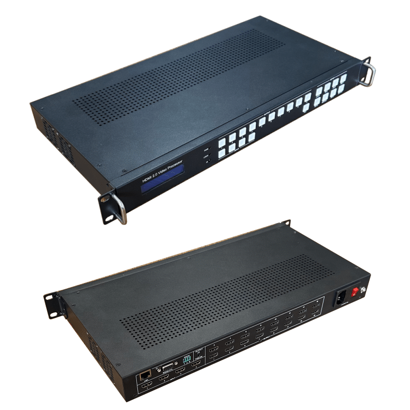
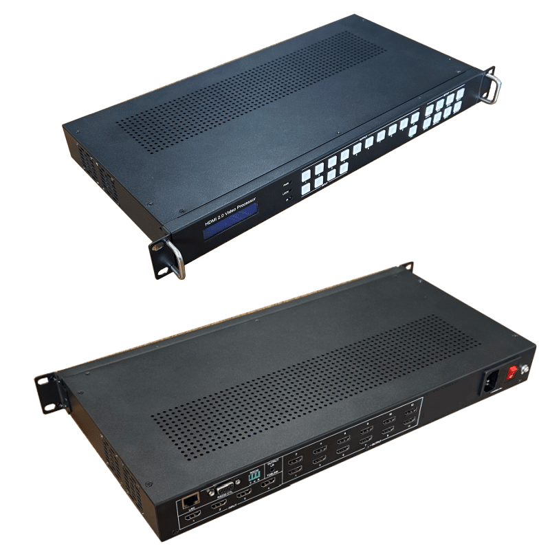
4 HDMI inputs,16 HDMI outputs,1 LR/Toslink(Spdif-Optical) audio output
Note: The audio output can be switched among IN1,IN2,IN3,IN4 via RS232 command or PC Tool
Application

Limitation
- There can be 4 groups of multiview display, output 1,2,3,4 can be the first group, output 5,6,7,8 can be the second group,output 9,10,11,12 can be the thirst group, output 13,14,15,16 can be the forth group.
If one output of one multiview group is enabled as multiview mode, then the other three will display the same content and output resolution
- If user want to display multiview video on a video wall, he must enable multiview function on output 13 and control the multiview layout on output 13 for the video wall multiview layout.
- If a video wall work in multiview mode, then input 4 can’t be a source for standalone output display or non-multiview video wall display.
- If a video wall work in multiview mode, the maximum screen number is 12, because output 13,14,15,16 need work in multiview mode and can’t be the member of video wall outputs.

Output Resolution list
| Hex Index | Output Resolution | Hex Index | Output Resolution |
| 00 | 4096x2160p 60Hz | 0C | 1920x1080p30 Hz |
| 01 | 4096x2160p 50Hz | 0D | 1680x1050p60 Hz |
| 02 | 3840x2160p 60Hz | 0E | 1600x1200p60 Hz |
| 03 | 3840x2160p 50Hz | 0F | 1360x768p60 Hz |
| 04 | 3840x2160p 30Hz | 10 | 1280x1024p60 Hz |
| 05 | 3840x2160p 25Hz | 11 | 1280x768p60 Hz |
| 06 | 3440x1440p 60Hz | 12 | 1280x720p60 Hz |
| 07 | 2560x1600p 60Hz | 13 | 1280x720p50 Hz |
| 08 | 2560x1440p 60Hz | 14 | 1024x768p60 Hz |
| 09 | 1920x1200p 60Hz | 15 | USER |
| 0A | 1920x1080p 60Hz | 16 | AUTO |
| 0B | 1920x1080p 50Hz |
Specification
| Band Width | 594MHz (18Gbps), HDMI 2.0, HDCP2,2 |
| Audio Format | LPCM 2.0 |
| Input ports | 4 HDMI |
| Output ports | 16 HDMI, 1 Mini Toslink port |
| Power Supply | 110-240VAC |
| Power Consumption | 75W Max |
| Operating Temperature | 0 to +40°C (+32 to +104 °F) |
| Operating Humidity | 10 to 70 % RH (non-condensing) |
| ESD | Air: ± 8KV, Contact: ± 4KV, |
| Dimensions | L430 x W220 x H44 mm |
| Mass | 5kg |
Package Contents
| Item | Quantity |
| Main Unit | 1 |
| AC Power Cord | 1 |
| USB to RS232 cable | 1 |
| 1 meter RJ45 cable | 1 |
PC Tool user guide
This PC tool is an installation free control software. It is divided into seven tabs according to different functions: Connect, Matrix, Signal, TV wall, System, and Multiview
The initial login password is: 111111
Connect tab
Please note:
- Use serial cable (straight line) or Ethernet cable
- When using a serial port connection, the network port connection must be disconnected, and vice versa
- When connecting through the network port, you must first search for and select the device before connecting

Matrix Switch Tab

Signal Tab
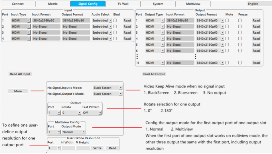
TV Wall Tab
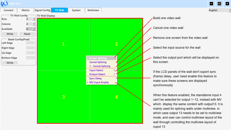
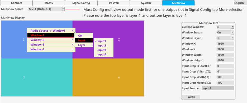
Multiviewer Tab
System Tab
How to achieve point to point display with LED panel
Step 1, connect input cable between source and one input port of the matrix switcher.
Step 2, connect output cable between LED panel and one output port of the matrix switcher.
Step 3, read the EDID of LED panel with PC Tool and download this EDID to the input port of the matrix switcher.
Step 4, set the output resolution of this output port as AUTO, or USER. When set USER, need configure the user define resolution first, and make the user defined resolution to match the physical resolution of the LED panel perfectly


