
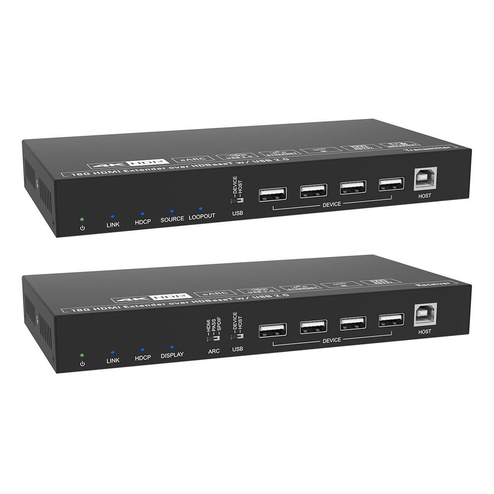
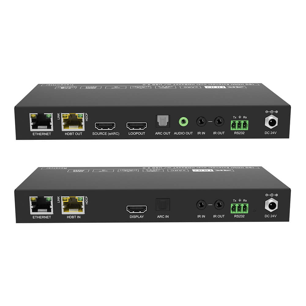
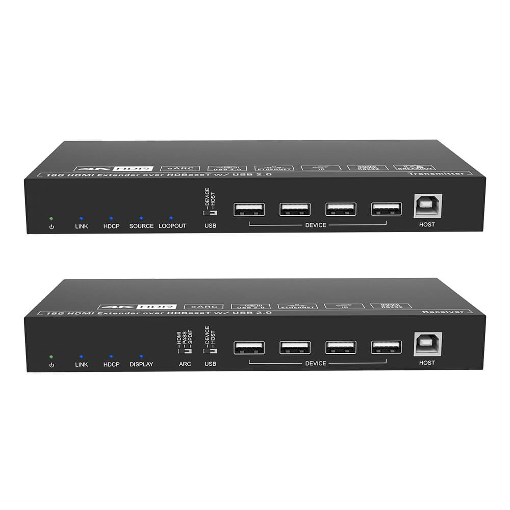
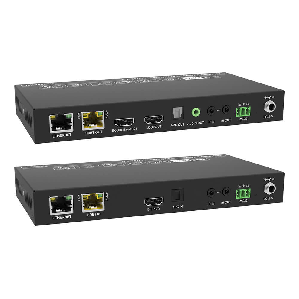
18G HDMI Extender, which consists of a transmitter and a receiver. It can extend 4K or 1080p video to distance up to 328 feet (100 meters) over a single CATx cable. It supports audio de-embedding and ARC. It also supports bi-directional IR, USB and RS232 pass-through control and Ethernet extension. 24V PoC feature allows the transmitter and the receiver can be powered from each other and only one power adapter is needed in system.
Features:
- 18Gbps high bandwidth.
- Supports HDMI 18Gbps and the HDMI video resolution up to 4K@60Hz 4:4:4, HDR.
- Supports HDCP bypass and HDCP 2.2 compliant.
- Extends 4K or 1080p video signals to distances up to 328 feet (100 meters) over a single CATx cable.
- Bi-directional IR, USB and RS232 pass-through control and Ethernet extension.
- Supports bi-directional 24V PoC.
- Supports audio de-embedding and ARC (Audio Return Channel).
- Provides HDMI loop out on transmitter.
Transmitter Interface

① POWER LED: Illuminates green when power is applied, or blinks when in firmware upgrade mode.
② LINK LED: Illuminates when there is a valid HDBaseT link between the transmitter and the receiver.
③ HDCP LED: Illuminates when the video contains HDCP content, or blinks whenthe video has no HDCP content.
④ SOURCE LED: Illuminates when there is an HDMI source device is connected to HDMI input port.
⑤ LOOPOUT LED: Illuminates when both HDMI source device and HDMI display device (HDMI loop out port) are connected.
⑥ USB: DIP switch for DEVICE or HOST mode selection.
l DEVICE: The USB devices at transmitter position are used to control the HOST PC at receiver position.
l HOST: The HOST PC at transmitter position is controlled by the USB devices at receiver position.
⑦ DEVICE: Four type-A USB 2.0 ports for USB devices (e.g. Mouse, Keyboard and Camera) connection to control the PC which is connected to the HOST port of receiver.
⑧ HOST: Type-B USB 2.0 port for PC connection. The PC can be controlled by the USB devices which are connected to type-A USB 2.0 ports of receiver.
Transmitter rear interface

① ETHERNET: Used for Ethernet extension together with the ETHERNET port of receiver.
② HDBT OUT: RJ45 port to connect the HDBT input port of receiver by CAT6A Ethernet cable. The LINK LED illuminates when there is a valid HDBaseT link between the transmitter and the receiver. The HDCP LED illuminates when the video contains HDCP content.
③ SOURCE: Connects to HDMI source device.
④ LOOPOUT: Connects to HDMI display device.
⑤ ARC OUT: Connects to audio player (e.g. amplifier) for ARC audio output.
⑥ AUDIO OUT: Connects to audio player (e.g. amplifier) for audio de-embedding from HDMI input.
⑦ IR IN: Connects to the IR receiver for IR pass-through.
⑧ IR OUT: Connects to the IR emitter for IR pass-through.
⑨ RS232: Connects to RS232 control device (e.g. PC) or a third-party device for RS232 control.
⑩ FIRMWARE UPGRADE BUTTON: Press the button with paper clip or other sharp tool for 3s to enter firmware upgrade mode. Press the button for 3s again can exit the mode.
⑪ DC 24V: DC connector for the power adapter connection.
Receiver interface

① POWER LED: Illuminates green when power is applied, or blinks when in firmware upgrade mode.
② LINK LED: Illuminates when there is a valid HDBaseT link between the transmitter and the receiver.
③ HDCP LED: Illuminates when the video contains HDCP content, or blinks when the video has no HDCP content.
④ DISPLAY LED: Illuminates when there is a HDMI display device is connected to HDMI output port and when input source is detected.
⑤ ARC: DIP switch for ARC mode selection.
l HDMI: The ARC input via HDMI output port of receiver.
l PASS: Supports CEC & ARC pass-through.
l SPDIF: The ARC input via SPDIF input port of receiver.
⑥ USB: DIP switch for DEVICE or HOST mode selection.
l DEVICE: The USB devices at receiver position are used to control the HOST PC at transmitter position.
l HOST: The HOST PC at receiver position is controlled by the USB devices at transmitter position.
⑦ DEVICE: Four type-A USB 2.0 port for USB devices (e.g. Mouse, Keyboard and Camera) connection to control the PC which is connected to the HOST port of transmitter.
⑧ HOST: Type-B USB 2.0 ports for PC connection. The PC can be controlled by the USB devices which are connected to type-A USB 2.0 ports of transmitter.
Receiver rear interface

① ETHERNET: Used for Ethernet extension together with the ETHERNET port of transmitter.
② HDBT IN: RJ45 port to connect the HDBT output port of transmitter by CAT6A Ethernet cable. The LINK LED illuminates when there is a valid HDBaseT link between the transmitter and the receiver. The HDCP LED illuminates when the video contains HDCP content.
③ DISPLAY: Connects to HDMI display device.
④ ARC IN: Connects to ARC audio source device (e.g.TV).
⑤ IR IN: Connects to the IR receiver for IR pass-through.
⑥ IR OUT: Connects to the IR emitter for IR pass-through.
⑦ RS232: Connects to RS232 control device (e.g. PC) or a third-party device which is to be controlled.
⑧ FIRMWARE UPGRADE BUTTON: Press the button with paper clip or other sharp tool for 3s to enter firmware upgrade mode. Press the button for 3s again can exit the mode.
⑨ DC 24V: DC connector for the power adapter connection.
System Connection
1) When ARC switch is selected to HDMI, and the TV supports ARC, the TV audio can be transmitted back to the transmitter via HDMI output port of receiver, and then it will be output by the ARC OUT & HDMI Source port of transmitter. CEC pass-through is not supported in this mode.
2) When ARC switch is selected to SPDIF, the audio can be transmitted back to the transmitter via ARC IN port of receiver, and then it will be output by the ARC OUT & HDMI Source port of transmitter. Besides, it also supports CEC pass-through in this mode.
3) When ARC switch is selected to PASS, the extender can pass the ARC signal and support CEC pass-through. If the amplifier can work with the TV for ARC function, the ARC audio can be transmitted back to the transmitter via HDMI output port of receiver, and then it will be output by the ARC OUT & HDMI Source port of transmitter.

Note: Please try to restart the extender if ARC function works abnormally.
4) BYOD PC or Dedicated Room PC mode connection


Specification


Note: Please use high-qualified HDMI cable fully compliant with HDMI V2.0 for reliable transmission and connection.


