18Gbps HDMI 2.0 2X9 Video wall Processor

1. Introduction
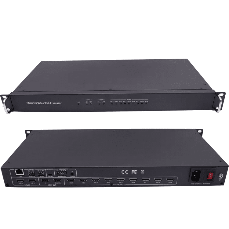
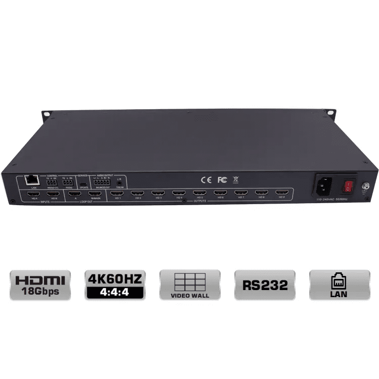
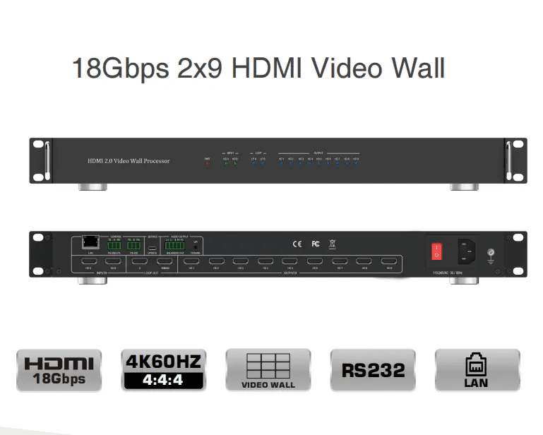
This product is an HDMI 2.0 Video Wall controller with 2 HDMI inputs, 2 HDMI loop outputs
and 9 HDMI scaling outputs for video wall processing. The Toslink jack terminal provides
analogue L/R audio and digital SPDIF audio output. 5-pin phoenix jacket provides balanced
L/R audio output. The product also supports RS-232 bypass feature for daisy chain and
cascade connection among different units.
1)HDMI 2.0 and HDCP 2.2 compliant
2)Support multi-resolution up to 3840×2160@60Hz video output for video wall
3) Support Bezel Compensation with two modes
4) Support 2 channels HDMI loop out
5) Support PIP on video wall
6) Support 180º rotation
7) Support RS-232 and TCP/IP control
8) Support CEC control with displayers by PC Tool or commands
Tech Support Tips:
Larger video wall configurations requiring multiple units can ONLY be setup and controlled via RS-232.
When multiple units need to be connected for larger video wall configurations, once the device is given a Device ID of 2 or greater is provided to the unit, it will need to be connected to the first unit in order to be controlled or accessed through the software.
Please ensure your source input resolution are set to a resolution OTHER than 720P/1280×720 when creating a video wall.
To prevent overheating when using multiple units, make sure you provide ample spacing between units of at least 1inch/25mm.
1 x Ultra HD Video Wall Processor
1 x AC Power Cord
1 x 5-pin Phoenix Connector
2 x 3-pin Phoenix Connector
1× RS232 to Phoenix Cable
1× CAT6 cable
1× USB to RS232 Cable
1× User Manual
SPECIFICATION
| Technical |
| HDMI compliance | HDMI 2.0 |
| HDCP compliance | HDCP 2.2 and HDCP 1.4 |
| RS232 | Baud rate 57600,data bit 8, Stop bit 1,no parity |
| Input Video Resolutions | 4096x2160p 24/25/30/50/60Hz–1400×1050 60Hz 3840x2160p 24/25/30/50/60Hz–1366×768 60Hz 1080p 24/25/30/50/60Hz–1360×768 60Hz 1080i 50/60Hz 1920×1200 60Hz– 1280×1024 60Hz 1280×960 60Hz 1680×1050 60Hz–1280×800 60Hz 1600×1200 60Hz—1024×768 60Hz 1440×900 60Hz–1280x720p50/60Hz |
| Audio Format | 2.0 channel, 5.1 channel, LPCM, Dolby, AC3, DTS |
| ESD Protection | Human-body Model: ±8kV (Air-gap discharge) , ±4kV (Contact discharge) |
| Mechanical | |
| Housing | Metal Enclosure |
| Color | Black |
|
| Weight | |
| Power Supply | Input: DC 12V/3A. Support DC5-12V wide voltage power supply; Output with overcurrent protection function |
|
| Power Consumption | 25W (Max) |
| |
| Storage temperature | -20°C ~ 60°C / -4°F ~ 140°F |
| |
| Relative Humidity | 10 – 50% RH (no condensation) |
| |
| Operation Temperature | 0°C ~ 40°C / 32°F ~ 104°F |
| |
| Dimensions | 430mm(W) × 220mm(D) × 44mm(H) |
Below is the Setup for reference
Step 1: Download the Free Software
If you haven’t already done so, Please contact us now.
Step 2: Establish Communication Between VideoWallProcessor and PC
Ensure effective communication between your PC and the VideoWallProcessor by following these options:
RS-232 Connection:
Select ‘UART’ as your control mode and enter the correct Port. The port should fill in automatically if the connection is recognized. If not, check your Device Manager. Click ‘Find via UART’ to locate your VideoWallProcessor.
Network Connection (Direct or Indirect):
To access the ‘Network Settings’, enter [ctrl+shift+F2] on your keyboard while the software is open.
Choose ‘Network’ as your control mode.
Ensure both your VideoWallProcessor and PC are on the same network scheme.
Adjust the VideoWall Processor’s IP address to match your network scheme using the ‘Network Setting’ tab in the software. For direct connections, set a static IP address within your PC’s IP range. For connections through a network switch or router, select ‘Auto IP (DHCP)’ to enable automatic IP address assignment. Save the configuration and reset the device.
Step 3: Configuring the Video Wall
Once communication is established, proceed to configure your video wall:
Click on the ‘Video Wall’ tab in the software.
Determine the layout of your video wall using the slider to adjust the number of TVs in each row and column.
Click ‘Set’ to apply your configuration.
Select and drag your mouse over all boxes to change their colors, then right-click to enable ‘Screen Splicing’. The boxes should turn green, indicating a unified display across all screens.
To switch inputs, right-click and select ‘Input Select’.
Adjust input and output resolutions and formats in the ‘Signal Setting’ tab if necessary.
Ensure ‘Fit to Screen’ is enabled on all TVs in the picture settings if the bezel appears misaligned.
Conclusion
With this guide, you should have successfully set up your video wall and made the necessary adjustments for optimal performance. Should you encounter any issues, don’t hesitate to contact 1@sz-sinowell support for assistance.